
Business Development
sales@steinel.ch
+41 55 418 21 11


Sensor development using Confusion Matrix
As a supplier of complete sensor solutions, STEINEL Solutions AG has many years of experience in the development and production of sensors in a wide range of industries. Successful implementation is based not only on experience but also on the Confusion Matrix methodology.
The definition of the use case
The detection behavior of a sensor application is decisive for the success of the product. The different application situations, so-called use cases, define the behavior of the sensor and describe how the sensor should react in each case. Not only the ideal case is considered, but all environmental factors.
STEINEL Solutions AG has brought successful sensor solutions to market in many industries. As a result, different application situations and solutions, such as in the field of people detection, are already known and implemented. If a new application deviates from existing solutions or new use cases are added, a joint development process between product owner and implementation partner begins.
• The product owner knows the industry-specific application and environmental conditions of his product. He specifies the requirements and the desired behavior, can also describe unfavorable installation situations thanks to his experience, interprets test results of the first prototype, and derives measures from them.
• The implementation partner develops the optimal solution with its broad expertise. This is usually an embedded system with sensors and actuators or any communication interfaces.
An iterative process in the intensive validation of early functional samples and more mature prototypes brings sensor optimizations and product improvements to light. In some cases, even use cases are only redefined in the course of this phase. Before the project moves on to industrialization, the requirements are coordinated with the test descriptions on the basis of a test plan and then verified point by point.
The design of the sensor characteristic by means of Confusion Matrix
The design of the sensor characteristics is supported by the Confusion Matrix, which has its origin in Machine Learnig models. With the confusion matrix, also called error matrix, the detection behavior and the limits of sensors are described clearly.
Using the example of a motion sensor, such as is used in outdoor areas of buildings, the Confusion Matrix in Figure 2 describes a passive infrared (PIR) sensor. It is often advisable to define the frequency of occurrence of the individual use cases in percentages with the product owner and to set them to an acceptable value, e.g., false negatives of up to 0.5% are tolerable. True POSITIVE: These cases are usually quickly defined and reflect the actual function of the sensor. They are the situations that the sensor should detect. A motion sensor detects people walking in front with a speed of >2km/h and switches on the light.
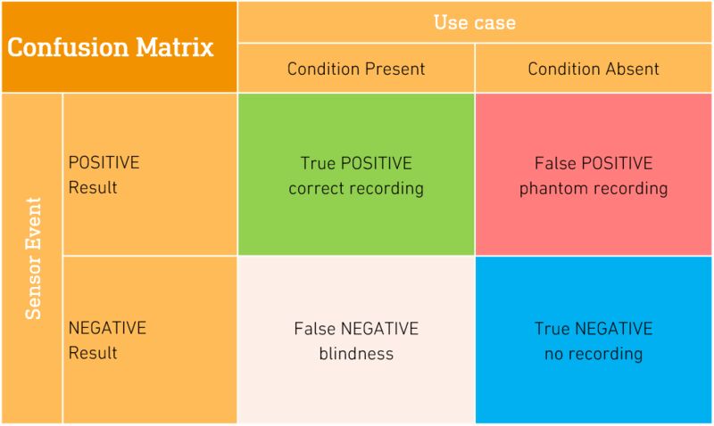
Figure 1 General representation of a Confusion Matrix, own representation
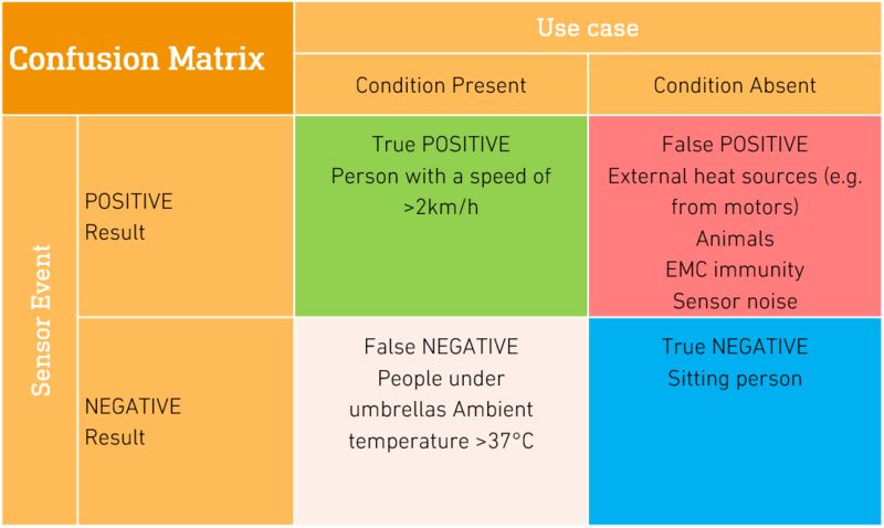
Figure 2 The cases are illustrative examples for the under-standing of the matrix and do not represent a real sensor.
True NEGATIVE: Seems quite obvious at first glance. Is it the opposite of True POSITIVE? Simply put, the motion detector should not detect a person in its detection zone who is not in the room. But what about a seated person who is not moving? In this case, a motion detector is actually called True NEGATIVE. In practice, a distinction is made between presence sensors (typically used in offices) and motion sensors. This explains that the motion sensor, unlike the presence sensor, does not react to a sitting person. On the other hand, it has a greater range and less expensive components.
Further there are two fields False POSITIVE (phantom detections) and False NEGATIVE (blindness). Both cases describe a malfunction of the sensor. The product owner and the development partner must agree on the degree to which such malfunctions are permissible. This delimitation is very individual and can have an influence on development and product costs. For example, additional sensor technology may be required to reliably detect specific special cases. Whether the application accepts the extra price of the additional principle is ultimately up to the product owner's price-performance assessment.
The interaction of many disciplines in the implementation
In the technical implementation of a sensor application, many specialist areas come together: analog design, digital filtering and signal processing, EMC immunity, power management, communication connections, alignment and calibration, etc. All these areas require appropriate expertise, infrastructure and tools to design the adaptation to customer-specific solutions based on existing technology building blocks. STEINEL has specialized in the field of PIR, high-frequency and optical sensors and has become the market leader. Its experience and resources in hardware and firmware development, PCB design, mechanical development, application testing and manufacturing and process know-how are correspondingly extensive.
A sensor usually contains an analog circuit. This already makes the PCB a tailor-made component. For this purpose, the PCB designer works out the optimal layout in close coordination with the hardware developer. Furthermore, the sensor must be protected from environmental influences and makes demands on its assembly - due to the technology or as defined by the product owner. These aspects flow into a mechanical design, which in turn entails requirements for production processes. Here, the interaction between design and production is a central process that should not be underestimated and which eliminates critical interfaces in a solution developed and produced inhouse.
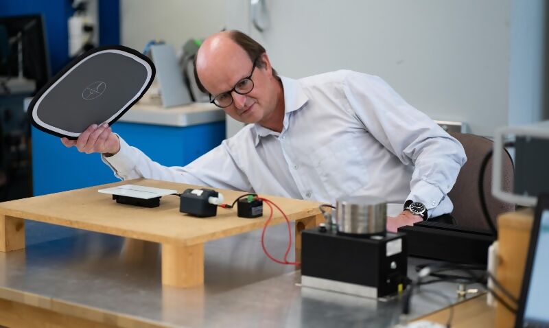
Figure 3 Andreas Münger in the EMC laboratory.
The firmware is a very central part in a sensor. Analog sensor signals are digitally converted and filtered and processed in a microcontroller. In autonomous sensors, the firmware processes the information from the sensor and controls an actuator, for example a valve for a washbasin fitting.
In a networked application, the sensor information is made available to a higher-level system via an interface. This allows spatially distributed sensors to provide much more complex detection behavior. With the wide range of communication technologies, sensors have evolved strongly in the direction of IoT (In-ternet of Things) in recent years. A wide range of implemented solutions allows STEINEL to select the right technology for a variety of use cases.
Sensors powered by a battery should function autonomously over a long period of time. Low-power applications are the rule today. Battery management can be just as much a part of this as sophisticated powersaving tricks.
Another discipline that should not be underestimated is the standard-compliant implementation and certification of the product. With a sensor, EMC immunity is always considered a critical area. STEINEL Solutions uses inhouse pre-compliance tests in its own EMC laboratory to optimize the False POSITIVE and False NEGATIVE. The solution often lies in clever signal processing in the firmware, which ultimately also results in cost neutrality for the product. Close coordination between hardware and firmware development is crucial for an optimum overall solution.

«What fascinates me about sensors as a developer is the extreme breadth of specialties that are necessary. Many years of experience enable me to implement hardware and firmware myself and to find optimal solutions in both areas. A good understanding of the application in the market is a prerequisite for this.»